
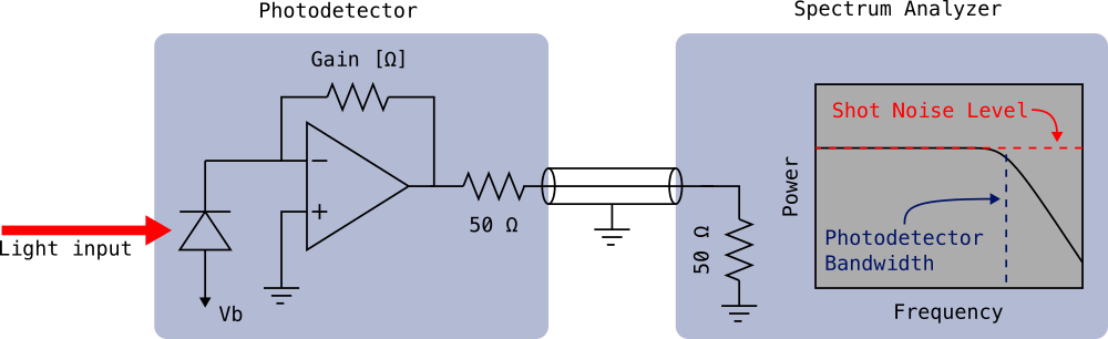
Note: There is a voltage divider formed by the 50Ω output impedance of the TIA and the 50Ω input impedance of the spectrum analyzer. This divider reduces the gain by a factor of 2. So for a photodetector with a gain of \(Z_\text{TIA}\) when connected to a 50Ω load, the value of the feedback resistor is \(2 \cdot Z_\text{TIA}\).
Calculate total input-referred noise including Johnson noise and op-amp noise contributions.
The shot noise level on a spectrum analyzer is calculated using the following formulas:
1. DC Photocurrent:
\[ I_{\text{dc}} = P_{\text{optical}} \times R \]
2. Shot Noise Current Density:
\[ i_n = \sqrt{2eI_{\text{dc}}} \quad \text{[A/}\sqrt{\text{Hz}}\text{]} \]
3. Noise Level on Spectrum Analyzer:
\[ P_{\text{dBm}} = 10 \log_{10}\left(\frac{(i_n \cdot Z_{\text{TIA}})^2 \cdot \text{RBW}}{50\,\Omega \times 1\,\text{mW}}\right) \]
where \(e = 1.602 \times 10^{-19}\) C (elementary charge), \(Z_{\text{TIA}}\) is the transimpedance gain, and RBW is the resolution bandwidth of the spectrum analyzer.
Responsivity Conversion (Optional): If you don't know your photodiode's responsivity directly but have its quantum efficiency and operating wavelength, you can use the optional calculator above. It converts using:
\[ R = \frac{\eta \lambda}{1240} \quad \text{[A/W]} \]
where \(\eta\) is quantum efficiency (as a fraction, 0-1) and \(\lambda\) is wavelength in nanometers.